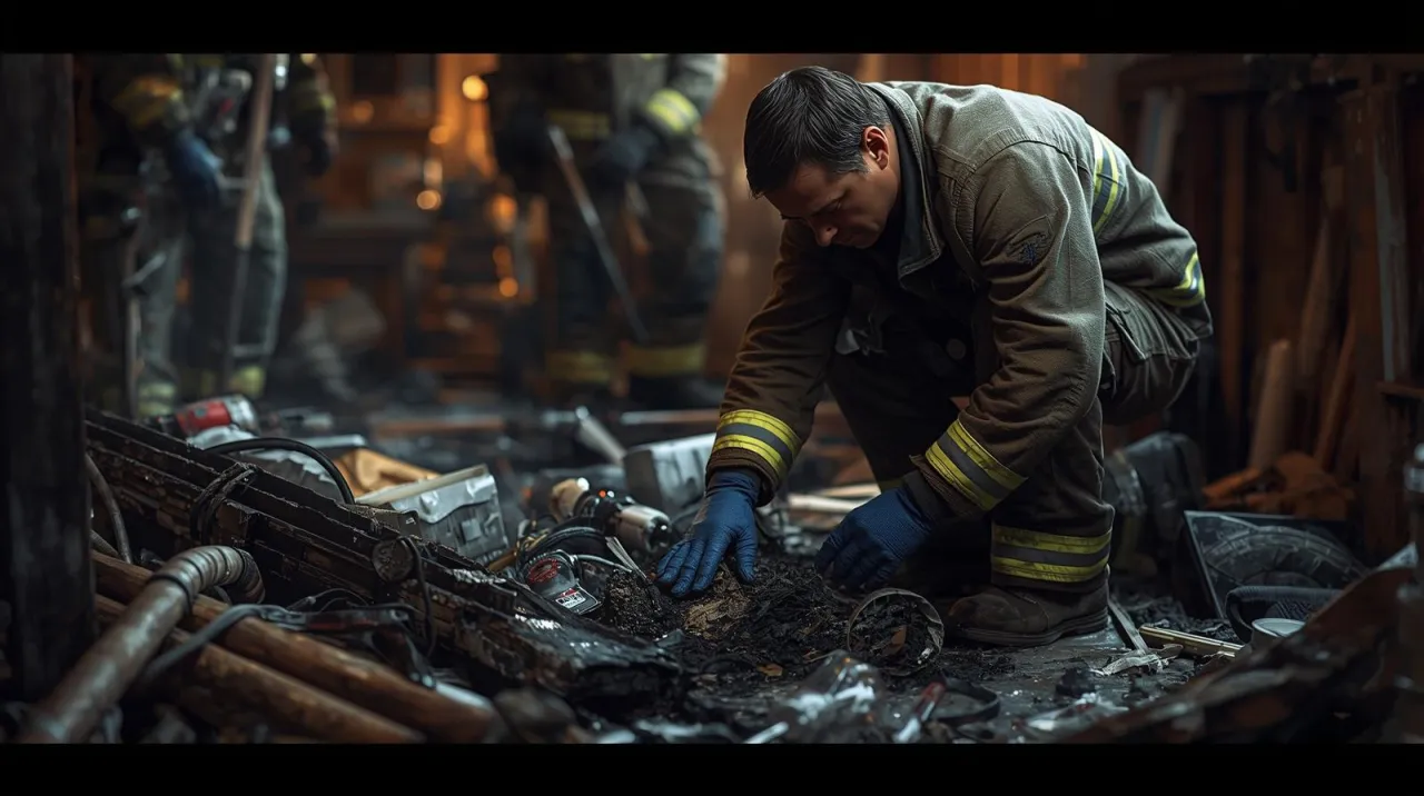

Why Electrical Fire Investigation Matters
Electrical failures are one of the leading causes of residential structure fires in the United States, accounting for tens of thousands of fires annually according to NFPA data. For fire investigators, determining whether electricity caused a fire, contributed to it, or was simply damaged by it requires a disciplined, evidence-based methodology.
This guide walks through the core process: understanding electrical fire indicators, applying arc mapping, following NFPA 921 guidelines, and collecting court-admissible evidence — whether for an insurance investigation, civil litigation, or criminal prosecution.
Step 1: Scene Approach and Safety
Before any analysis begins, the scene must be safe. Electrical systems should be confirmed de-energized by the utility — not just the breaker. Residual charge in capacitors, uninterruptible power supplies (UPS), and solar panel systems can remain hazardous long after main power is disconnected.
Establish your area of origin hypothesis early based on burn patterns, char depth, and witness accounts, but treat it as a working theory only. Electrical evidence can shift the origin determination significantly during analysis.
For ongoing scene documentation across multiple operational periods, the Fire Watch Log Generator provides a printable timed log sheet that keeps access records and hazard notes organized.
Step 2: Arc Mapping
Arc mapping is the systematic identification and plotting of all arc sites found throughout the fire scene. An arc site is any location where electrical conductors have fused, beaded, or melted in a pattern consistent with arcing activity.
Investigators examine:
- Conductors — branch circuit wiring, extension cords, appliance cords
- Receptacles and outlets — look for pitting, heat discoloration, and melted contact points
- Breakers and panels — trip status, heat damage, arc marks on bus bars
- Appliances — internal wiring, heating elements, motor windings
Each arc site is documented with photographs, measurements from fixed reference points, and conductor samples for lab analysis. The completed arc map is then plotted on a floor plan diagram to visualize the energized circuit paths during the fire.
Step 3: Cause-Related vs. Fire-Induced Arcing
The most critical distinction in electrical fire investigation is separating cause-related arcing from fire-induced arcing. This is the central guidance of NFPA 921, the recognized standard for fire and explosion investigation in the United States.
| Type | When It Occurs | Investigative Significance |
|---|---|---|
| Cause-related arcing | Before ignition — the electrical event that starts the fire | Confirms electricity as heat of ignition |
| Fire-induced arcing | After ignition — fire heat destroys insulation, conductors contact and arc | Does not indicate electrical cause |
Key differentiators include the location of arc sites relative to the area of origin, whether arc damage is consistent or inconsistent with overall fire progression, and metallurgical analysis of conductor samples — bead morphology and grain structure.
Step 4: Common Electrical Fire Indicators
Investigators look for the following physical evidence at electrical fire scenes:
- Copper beading — rounded globules on conductor tips caused by arcing; shape and surface texture help indicate whether the arc preceded or followed general fire damage
- Copper migration — copper deposits found inside insulation, indicating sustained heat at that location
- Melted insulation patterns — localized melting inconsistent with radiant heat from the general fire
- Breaker trip patterns — a tripped breaker does not confirm an electrical cause but is significant; a breaker that did not trip despite severe conductor damage may indicate a fault below trip threshold
- Appliance internal damage — disproportionate internal heat damage in a specific appliance component relative to surrounding fire damage
Step 5: Load History and Witness Interviews
Physical evidence alone is rarely sufficient. Investigators reconstruct the electrical load history of the building prior to the fire:
- Which appliances were in use in the hours before ignition
- History of tripped breakers, flickering lights, or burning smells — classic overload indicators
- Recent electrical work, permitted or unpermitted
- Extension cord use, especially multi-tap adapters or cords running under rugs
- Utility company records showing power fluctuations or outage events
Witness interviews should follow a structured approach — open-ended questions first, then specific follow-up. Statements about appliance usage, the location of the first flame or smoke, and any unusual electrical behavior are critical data points.
Step 6: Evidence Collection and Chain of Custody
Electrical evidence is fragile. Conductors, receptacles, and appliance components must be collected, packaged, and documented carefully to preserve forensic value:
- Photograph in place before collection
- Use clean, non-conductive packaging — avoid plastic bags that trap moisture and cause further oxidation
- Label each item with scene location, circuit identification, and collector name and date
- Maintain chain of custody documentation for any sample that may be used in litigation
For scenes involving electrical equipment with hazardous material concerns — industrial capacitors, lithium battery fires, or PCB-containing transformers — the Hazmat Hub provides quick-reference DOT class information and first-action guidance.
NFPA 921 and the Scientific Method
NFPA 921 requires investigators to apply the scientific method: collect data, form hypotheses, test those hypotheses against all available evidence, and revise conclusions when the evidence demands it. Confirmation bias — finding electrical evidence and stopping the analysis — is explicitly addressed as an investigative failure.
For a structured overview of NFPA 921 and related standards, the NFPA Standard Explorer provides searchable summaries of 65+ standards including NFPA 921 and NFPA 1033.
Key standards for electrical fire investigation:
- NFPA 921 — Guide for Fire and Explosion Investigations
- NFPA 1033 — Standard for Professional Qualifications for Fire Investigator
- NFPA 70 (NEC) — National Electrical Code, essential for understanding installation standards and code violations
For Fire Science Students
If you are studying fire investigation as part of a fire science curriculum, prioritize these foundational skills before working live scenes:
- Residential wiring systems — service entrance, panel, branch circuits, grounding
- Reading circuit diagrams and understanding load calculations
- Arc fault and ground fault circuit interrupter (AFCI/GFCI) operation and failure modes
- The NFPA 921 scientific method framework applied to real case studies
- Courtroom testimony preparation — fire investigators are frequently called as expert witnesses in civil and criminal cases
For quick definitions of fireground and investigation terminology, the Fireground Operations Glossary covers 99 operational terms used across suppression, command, and investigation contexts.
Comments 0
No comments yet. Be the first to share your thoughts!
Leave a Comment