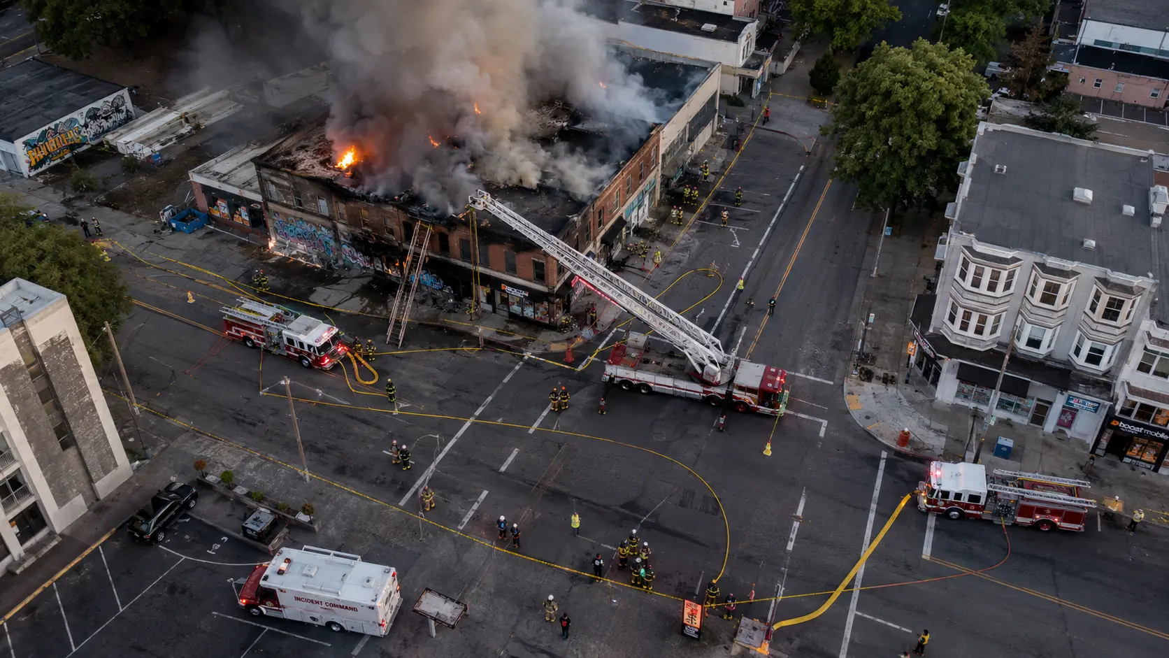

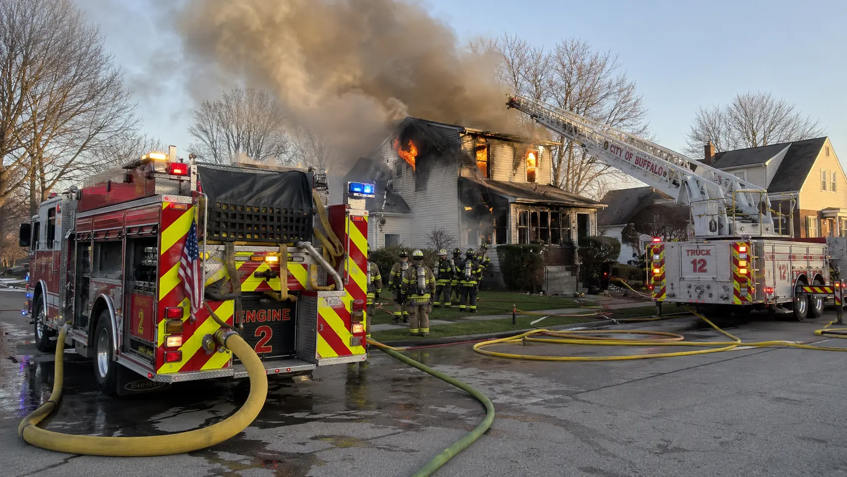
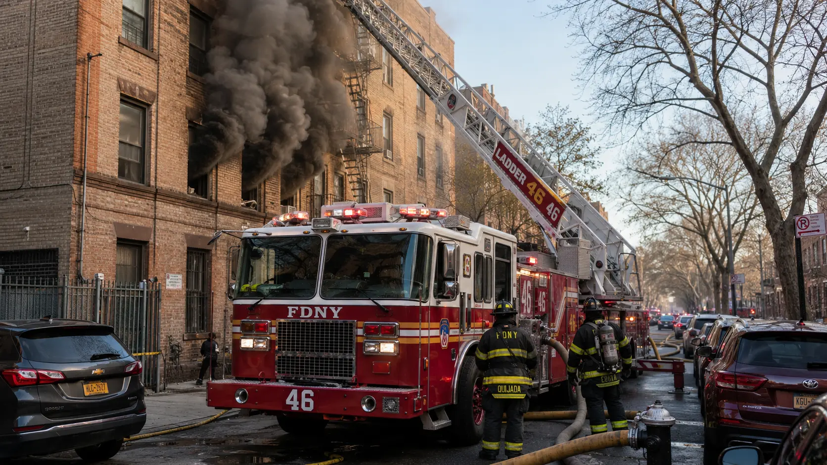
The first engine officer to arrive at a working structure fire parks the apparatus and every unit that arrives after it works around that position. If the engine is in front of the main door, the ladder cannot position optimally for the aerial. If the engine is over the hydrant, the supply must come from the next hydrant down the street. If the engine is between the building and where the collapse zone should be, it cannot move once the hose is laid and charged. The positioning decision happens in seconds and its consequences last for the duration of the incident.
Most positioning problems at working fires are not caused by bad luck. They are caused by first-arriving officers focusing on the fire and the building — the obvious tactical priorities — without simultaneously processing the access geometry that will determine whether the second, third, and fourth company can do their jobs effectively.
In this article:
- Collapse zone: calculating where not to be
- Engine positioning: hydrant access and approach angle
- Aerial positioning: the angle that determines reach
- The approach sequence for multiple companies
- Urban positioning constraints
- Exposure building positioning
- The specific mistakes and their consequences
- High-rise positioning
Collapse Zone: Calculating Where Not to Be
The collapse zone is the area adjacent to a burning structure within which wall or facade failure would be immediately fatal to anyone present. For most residential wood-frame and masonry construction, the minimum collapse zone radius is equal to the building's height — a 30-foot-tall building has a minimum 30-foot collapse zone. For buildings with specific collapse risk factors — deteriorated masonry parapets, compromised load-bearing walls visible from exterior, previous fire damage — the zone is extended.
Apparatus positioned inside the collapse zone at the start of operations cannot move safely once hose lines are charged and deployed. A 30,000-pound engine sitting inside the collapse zone of a building that subsequently collapses is not a problem that gets better over time. The apparatus may be trapped by falling debris, water from charged hose lines prevents the pump from being secured for movement, and the crew's attention is on operations rather than monitoring the building for collapse indicators.
The collapse zone calculation happens during the initial size-up — before any company commits to a position — and is reassessed when conditions change. A building that appears stable at arrival may show collapse indicators during the incident: bowing walls, audible cracking, fire involvement of load-bearing elements, smoke pushing from unexpected locations. Each of these indicators requires a re-evaluation of whether apparatus positioned earlier in the incident is now inside a collapse zone that has been extended by changing conditions.
Engine Positioning: Hydrant Access and Approach Angle
The first-due engine's positioning is driven by three simultaneous requirements: access to a water supply, an approach angle that allows hose advancement to the fire, and a position that does not block the second-due ladder company's aerial deployment lane.
The hydrant closest to the fire is not automatically the correct hydrant to connect to. The hydrant directly in front of the fire building may be the only hydrant that puts the aerial company's supply connection in conflict with the engine's position. Passing the closest hydrant and connecting to the one 150 feet further down the street can leave the closest hydrant available for the ladder company's aerial water supply — a decision that costs the engine 150 feet of additional supply hose and potentially 30 seconds, and prevents a positioning conflict that would take significantly longer to resolve.
The engine's approach angle to the building — the angle at which it parks relative to the building facade — determines how the hose beds can be laid and how quickly the attack crew can advance. An engine parked perpendicular to the building (pointed directly at the front door) positions the hose beds directly toward the target but occupies the aerial's lane directly in front of the building. An engine parked at 45 degrees allows hose deployment toward the door from a position that does not block the direct-front approach needed by the aerial.
Aerial Positioning: The Angle That Determines Reach
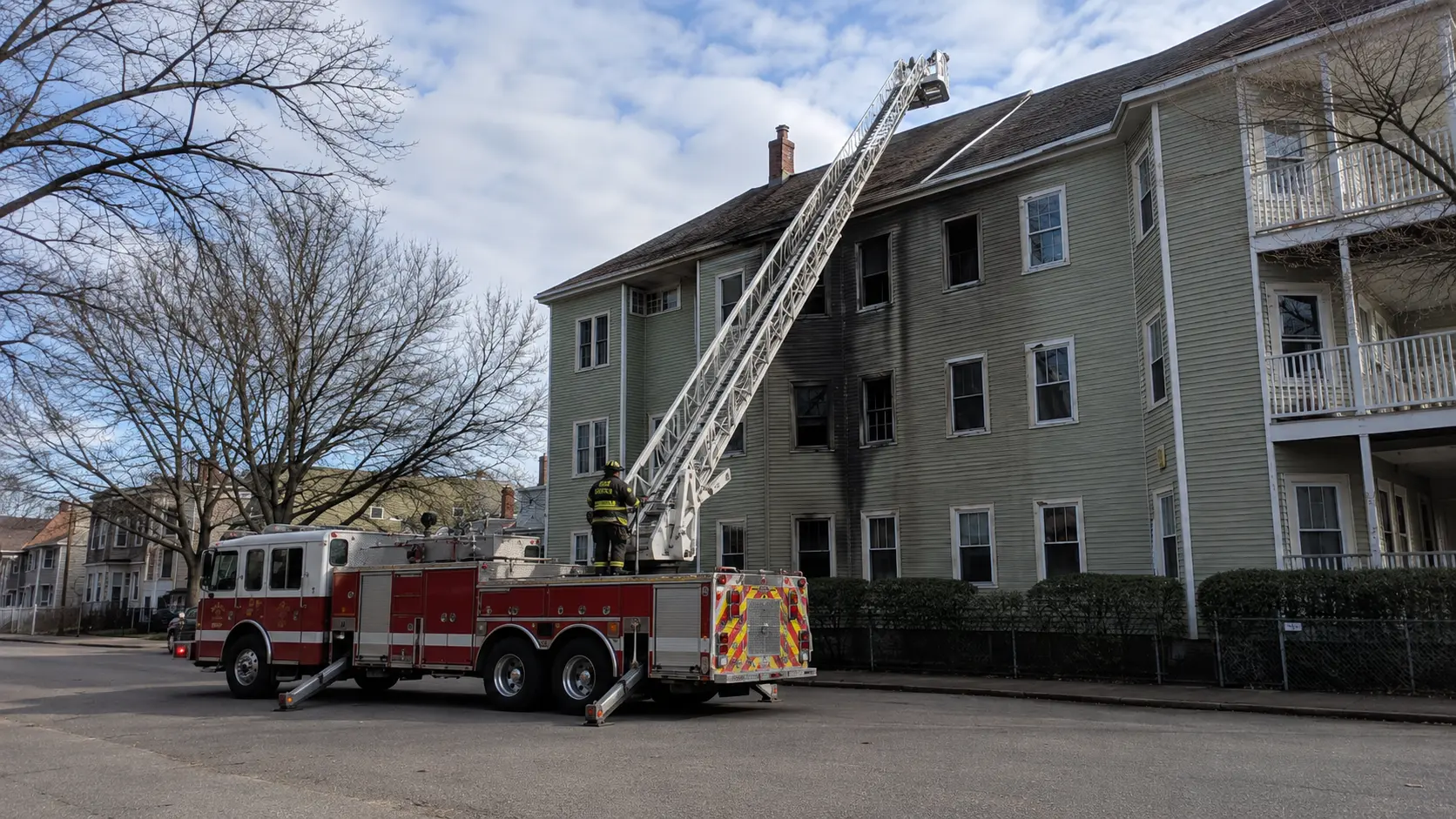
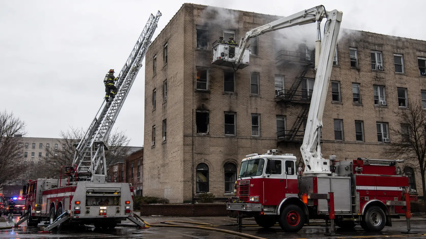
The aerial ladder's effective reach is determined by the elevation angle at which it is deployed. At approximately 70 degrees of elevation, the aerial achieves its maximum working length effectively — the balance between vertical reach and horizontal extension is optimized at this angle. As the elevation angle decreases below 70 degrees (to reach a building that is set back further from the street), the vertical reach drops and the horizontal load on the aerial extension increases. As the elevation angle increases above 70 degrees (close to the building), horizontal reach decreases.
The chauffeur's positioning decision has to account for the building's setback (distance from the curb to the building face), the presence of overhead obstructions (power lines, tree branches), and the intended rescue or operational point. Positioning the aerial too close produces an angle that is too steep to reach across the building face. Positioning too far produces an angle too shallow to achieve the required height. The calculation happens in seconds and must account for outrigger placement constraints — a surface that cannot support outrigger loads changes the effective positioning range.
The Approach Sequence for Multiple Companies
Departments with multiple companies responding to a working fire establish positioning protocols that assign each company a specific approach direction based on their arrival order. A typical protocol for a 2-engine, 1-ladder response:
- First engine (E1): Positions at 45 degrees to the building on the fire side, connects to the second hydrant down from the building face, advances attack line. Does not park in front of the main door or over the building-side hydrant.
- Ladder: Positions perpendicular to the building face, directly in front, using the building-side hydrant for aerial water supply connection. The aerial deploys toward the fire floor or roof.
- Second engine (E2): Positions on the opposite side from E1, or covers a specific exposure, connecting to a hydrant that provides a second supply line for the operation or for exposure protection.
This sequence is pre-established so that each company knows its position before it arrives — the second company does not wait to see where the first company parked before deciding where to position. Pre-established protocols allow simultaneous positioning rather than sequential negotiation, which reduces the time between arrival and operational readiness.
Urban Positioning Constraints
Urban positioning — narrow streets, parked cars, overhead obstructions, and buildings at the property line — produces positioning constraints that rural and suburban protocols do not address. The specific urban constraint problems:
- Double-parked vehicles: In dense urban areas, parked vehicles on both sides of a narrow street may leave insufficient width for apparatus approach. Departments have established apparatus widths and approach routes that account for typical parked vehicle configurations, and officers who deviate from those routes encounter positioning problems that pre-planning would have avoided.
- Overhead power lines: Aerial deployment beneath active power lines is prohibited. Many urban streets have overhead power lines that restrict aerial deployment on the street-facing side of buildings. The chauffeur must identify the last safe position along the approach that allows aerial deployment before the power line zone begins.
- Building setback zero: Buildings built at the property line, with no setback from the curb, require the aerial to be positioned at an angle that is nearly vertical to reach the upper floors — which reduces horizontal reach significantly. These buildings may be effectively unreachable by aerial ladder from the street, which drives the tactical decision toward other means of upper-floor access.
Exposure Building Positioning
When a fire threatens adjacent buildings — exposures — positioning must account for both the primary fire building and the exposures. An exposure that is receiving significant radiant heat or direct flame contact requires water application from a position that can reach the exposure's most threatened surface. This may conflict with the positioning required for primary fire attack.
The incident commander's positioning decision for exposure protection: prioritize the most threatened exposure and assign a company to cover it from a position that addresses that specific threat, while the primary attack companies position for fire suppression. Trying to position a single company to both attack the primary fire and protect an exposure from the same position produces inadequate coverage of both.
The Specific Mistakes and Their Consequences
| Positioning mistake | Consequence | Correction difficulty |
|---|---|---|
| Engine parked over the hydrant | Cannot connect supply without moving the engine; delays water supply | High — requires moving loaded apparatus, relocating hose |
| Engine parked directly in front of the door | Blocks aerial from front positioning; forces aerial to suboptimal angle | High — aerial is already deployed before the conflict is discovered |
| Apparatus inside collapse zone | Trapped by falling debris; crew in immediate danger if building fails | Very high — may not be correctable under active fire conditions |
| Aerial on wrong side of building | Cannot reach the fire floor window or the rescue point | High — repositioning requires lowering, repositioning, redeploying |
| Multiple engines connected to same hydrant | Reduces available pressure and flow to both; may cause supply failure | Moderate — second engine can relocate before charging |
High-Rise Positioning
High-rise positioning is simpler in some ways — the building is tall enough that aerial apparatus cannot reach upper floors, so the aerial positioning decision is primarily about coverage of lower floors and about positioning for elevated master stream capability rather than for rescue. The critical positioning decisions for high-rise operations shift to:
- Fire department connection (FDC) access — the standpipe connection that allows the engine to boost pressure to the building's standpipe system requires an engine positioned within hose reach of the FDC
- Command post location — outside the collapse zone, in a position with visual access to the building and radio communication with interior crews, and not blocking apparatus access or egress
- Staging area — a location removed from the immediate scene where additional responding resources can assemble without blocking the access corridor for vehicles that need to reach the building
- Egress route maintenance — high-rise incidents draw large apparatus responses; maintaining at least one unobstructed egress route for ambulances and for apparatus that may need to reposition is an incident management requirement that must be addressed from the first arriving company's positioning decision
Comments 0
No comments yet. Be the first to share your thoughts!
Leave a Comment